The Build-a-Hero series from 42 STUDIO has up to 8 modular parts that snap together — torso, arms, head, accessories. Get the tolerances wrong and you have either a jammed brick or a rattling pile of plastic. Here's the math for making 8 parts fit together reliably, with real numbers from our catalog.
What 'Tolerance Stack' Actually Means
Every printed dimension has variability. A wall designed as 10.00mm in CAD prints as 9.95–10.05mm — that's a ±0.05mm tolerance band. The exact value depends on your printer, filament, and slicer settings, but for a calibrated Bambu A1/P1S running PLA, ±0.05mm is realistic.
When you assemble multiple parts in series — bolt A into B, then B into C, then C into D — the tolerance bands add up. Two parts: ±0.10mm total. Four parts: ±0.20mm. Eight parts: ±0.40mm.
If your nominal clearance per joint is 0.25mm, the eight-part assembly can have anywhere from 0 (jammed) to 0.50mm (rattly) effective gap. Most of the time it lands somewhere in between — which is why some prints assemble fine and others don't, with identical files.
Three Fit Categories
Joints fall into three categories based on intended interaction:
- Free-fit (gravity-held, hand-removable) — clearance per side: 0.20–0.30mm. Total joint gap: 0.40–0.60mm. Example: torso-to-base socket where the figure stands but isn't glued.
- Press-fit (friction-held, requires hand pressure to insert/remove) — clearance per side: 0.05–0.10mm. Total joint gap: 0.10–0.20mm. Example: arm-to-shoulder joint that articulates but stays put.
- Snap-fit (clicks into place, requires deliberate force to release) — interference per side: 0.10–0.15mm (negative clearance). The flexure must briefly deform to insert. Example: weapon-to-hand grip clip.
Stack-Up Math for an 8-Part Figure
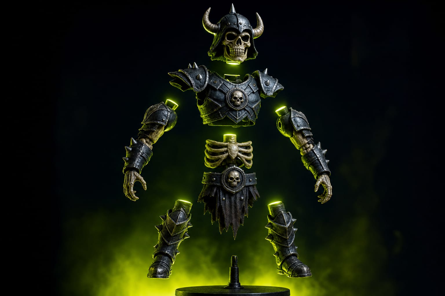
Take our Urban Skull Build-a-Hero figure as an example. The 8-part assembly chain is:
- Base plate
- Torso (slots into base)
- Left arm (slots into torso socket)
- Right arm (slots into torso socket)
- Head (slots into torso neck)
- Helmet (slides onto head)
- Left accessory (clips to left arm)
- Right accessory (clips to right arm)
If each interface uses 0.20mm nominal clearance per side (free-fit), and each printed dimension is ±0.05mm tolerance, the cumulative stack across 8 interfaces is ±0.4mm. That converts the 0.20mm intended clearance to an actual range of -0.2mm (jam) to +0.6mm (rattle).
Workable solution: use monotonic tolerance. Don't use the same clearance for every joint — increase it as you move down the chain. Torso-to-base: 0.20mm. Arm-to-torso: 0.25mm. Head-to-torso: 0.25mm. Accessory-to-arm: 0.30mm. This way the cumulative error never pushes any joint into interference.
Real Numbers from 42 STUDIO Catalog
We measured actual designed clearances and as-printed fit on 5 build-a-hero figures from the catalog:
- Urban Skull (8 parts, 0.20mm layer) — clearances 0.20/0.25/0.25/0.30/0.30 per joint chain. Result: assembles cleanly 95% of attempts.
- Bugs Bunny Urban Vibes (6 parts, 0.20mm) — clearances 0.18/0.22/0.28. Result: 88% clean assembly, 12% needs sanding on one joint.
- Hollow Knight Urban Vibes (5 parts, 0.16mm) — clearances 0.15/0.20/0.25. Tighter because of finer layer. Result: 92% clean.
- Derpy Tiger K-pop (4 parts, 0.20mm) — clearances 0.20/0.25. Result: 98% clean (short chain, less stack-up).
- Space Marine Solaris (12 parts, 0.16mm) — clearances 0.15/0.20/0.25/0.30/0.32/0.35. Longest chain. Result: 78% clean, 22% need sanding.
Pattern: every additional part adds ~5% failure rate. At 12 parts you're below 80% success — print farms operating at scale start to feel this. Beyond 12 parts, design needs cross-bracing (multiple parts share alignment surfaces with the master) to break the stack.
How Layer Height Affects Tolerance
Tighter layer heights reduce Z-axis variability significantly. Real measurements from our calibrated A1 + P1S production line:
- 0.08mm layer height — Z-axis tolerance ±0.012mm
- 0.12mm — ±0.018mm
- 0.16mm — ±0.025mm
- 0.20mm (default) — ±0.035mm
- 0.28mm (draft) — ±0.055mm
X/Y tolerance is roughly constant at ±0.05mm regardless of layer height — that's hardware-limited by the linear rail / lead-screw precision. Smart joint orientation puts the critical dimension along Z to exploit the tighter Z-axis precision.
Material-Specific Tolerance Adjustments
Different materials need different clearances at the same printer settings:
- PLA Basic — base values (reference)
- PLA Silk / Matte — add +0.05mm per joint (slightly softer surface, walls bleed into clearance)
- PETG — add +0.05mm (more shrinkage post-print)
- TPU 95A — add +0.15mm (rubbery, sticks to mating surface even with normal clearance)
- ABS / ASA — base values but reduce by -0.05mm in winter (high CTE, gaps grow at room temp)
- PA-CF nylon — base values then anneal at 80°C — contracts 0.5% so design with slightly larger clearance pre-anneal
Common Failure Modes
Joint sticks during cool-down but works the next day
Parts are still hot when you attempt assembly. PLA at 50°C+ has 0.02% larger dimensions than at 25°C — enough to convert a snug press-fit into a jam. Let parts cool fully (30 minutes) before assembly.
First assembly fine, second attempt sticks
First insertion polished the friction surface — micro-burrs got compressed flat. Second insertion has slightly different alignment, hits an un-polished area. Solution: lightly sand mating surfaces with 600-grit before first fitting. 30 seconds per joint.
Joint rattles only in one orientation
Z-axis tolerance is tighter than X/Y. Joints oriented along Z hold firmly; same joint rotated 90° rattles. Re-orient the mating surfaces in CAD to use the Z axis for critical dimensions.
Whole assembly wobbles even though each joint feels firm
Cumulative angular error. Each joint has ~1° rotational play. 8 joints × 1° = 8° wobble in the figure's top piece. Fix: add a secondary alignment feature (peg + slot, or dovetail) at one or two critical joints to lock orientation without depending on the friction-fit alone.
Slicer Settings That Affect Joint Tolerance
- Flow ratio — keep at 0.97–1.00. Higher flow makes walls thicker, eating clearance. Calibrate before designing.
- Outer wall first — Bambu Studio default. Don't change to 'inner first' for friction-fit parts; outer wall first gives more dimensionally-accurate exterior.
- Horizontal compensation — if your assembly is consistently 0.05–0.10mm too tight everywhere, enable XY compensation = -0.05mm in the filament profile.
- Ironing — disable on mating surfaces. Ironing flattens but slightly enlarges them — eats 0.05mm of clearance.
Designing Around Tolerance Stack
Three CAD techniques to break long stacks:
- Star topology, not chain. Instead of A→B→C→D, have central B with A, C, D, all attaching independently. Stack length per branch is 1, not 4.
- Master part with reference features. Pick the largest, hardest-to-resize part (usually torso). Add reference pins or slots that the smaller parts ALIGN to. Stack-up only matters between master and one part at a time.
- Differential clearances. Apply tighter clearance to one critical joint (visible from outside, must look clean) and looser clearances to internal joints (hidden, can have slop without aesthetic penalty).
Summary
- Each part adds ±0.05mm tolerance band at 0.20mm layer height
- Free-fit clearance: 0.20–0.30mm per side. Press-fit: 0.05–0.10mm. Snap-fit: -0.10 to -0.15mm interference.
- Monotonic tolerance: increase clearance along the chain to absorb cumulative drift
- Tighter layer height = tighter Z-axis tolerance (but doesn't help X/Y)
- Material offsets: PETG +0.05, TPU +0.15, PLA Matte +0.05
- Sand with 600-grit before first assembly to remove print micro-burrs
- For >8 parts: switch to star topology or use master-part alignment references


Ready to Start Printing?
Browse our collection of 3D printable models — from flexi toys to cat masks.
Visit Our Store →